
At ITC 2025, Rich Hoffman, an engineer with Delta Telemetry Systems (DTS), demonstrated the company’s End-to-End (E2E) Telemetry Ground Station, showcasing the seamless integration of IRIG218 Telemetry-over-IP (TMoIP) connected devices across the Delta Telemetry Systems family of products.
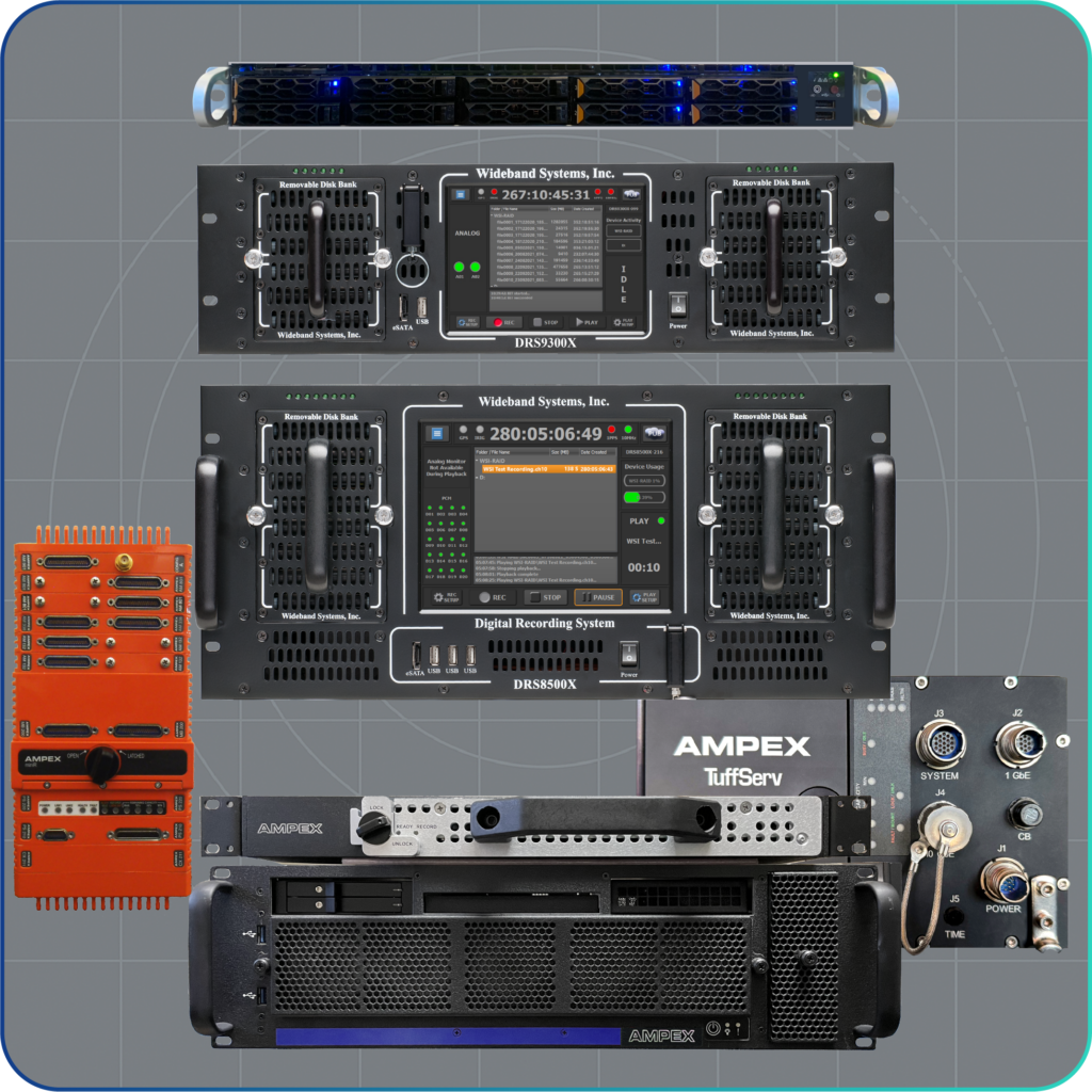
The E2E station was designed to highlight a complete telemetry signal chain. From a TCS antenna system through two GDP Model 4426 Dual Channel Receivers, a GDP Model 2355 Sixteen Channel Telemetry Gateway, one GDP Model 2267 Sixteen Channel Correlating Best Source Selector a Quad Stream Acroamatics 2510 Telemetry Data Processor (TDP), a GDP Model 3500 GDP Ethernet Recorder, and a Wideband DRS8200X Telemetry Recorder;
The Model 3500 Ethernet Recorder and the Model DRS8200X Telemetry Recorder are included to support record/playback of Ethernet data and PCM data to the system as two secondary paths. The entire system is set up, controlled, and real-time system status is provided via the DTS TRMS-RMS (Telemetry Range Management Software) package. Real-time processing and display of the PCM data parameters is provided via the powerful Acroamatics ADAT (Acroamatics Display and Processing Tool) software shown on the monitor attached to the top of the rack.
In this demonstration, the Simulator #3 (SIM3) in the Acroamatics TDP generates a 5 Mbps PCM Chapter 4 data stream that is fed into an S-Band transmitter (SIM3 Data & Clock) and modulated onto a PCM/FM carrier. The PCM/FM signal is then fed into a Quad RF Splitter/Programmable Attenuator, which cycles through each of the four RF channels one at a time and attenuates the PCM/FM signal that drives the four input channels of the two Dual Channel Receivers.
The receivers output two sets of DQE/DQM Encapsulated data streams, one set over Ethernet and one set of four data/clock outputs that drive the Model 2355 Telemetry Gateway, which sends this data over Ethernet. Both sets of four streams with SIM3 data are input to the Model 2267 Correlating Best Source Selector over Ethernet in two separate groups. The programmable attenuator cycles through and attenuates each RF channel one at a time, causing the BSS to switch from channel to channel.
The two Group outputs of the BSS, both outputting the combined SIM3 data stream, drive the TDP on Ethernet input channels 1 & 2, which is processing and displaying the PCM data parameters on a variety of ADAT displays at the top of the rack, showing in real time that the data through the Correlating BSS has no drops while switching. This is illustrated in a variety of strip chart displays with no interruptions.
A secondary set of two simulated streams (both from Simulator # 4 of the Acroamatics TDP) is recorded and played back in a loop as PCM (data/clock) through the Wideband Baseband Telemetry Recorder into streams 3 and 4 (PCM) of the Acroamatics TDP. All 4 streams are displayed on the monitor at the top of the rack.
Rich explained how each component communicates through a common network backbone, allowing operators to monitor link status, data rates, and signal quality in real time. Together, the demonstration captured the “Acquire to Display & Analyze” telemetry chain that defines DTS’s End-to-End solution: connecting antennas, receivers, gateways, recorders, processors, and displays into one interoperable, IP-based system for mission-critical flight test and range applications.
Each ITC station was paired with an interactive touchscreen display designed to give attendees a deeper look into the technologies behind every demo. These touchscreens provided a guided walk-through of each system’s components, showcased top products, and highlighted key advantages from the company.
Explore the same content for yourself.
